The (tr)uSDX has hardware to measure the power amplifier voltage/current/input power. Since the output power is also measured, it can calculate and show efficiency. This is very useful for tuning the class-E output stage, and is also useful in the field to see battery voltage and other parameters.
I have an uSDX+ transceiver from China. Let’s add the power monitor to it too. This description should apply to other radios based on the uSDX.
To make this mod you need some manual and soldering skills, a basic understanding of electronics, and the ability to compile and flash your own firmware through the 6-pin ISP connector. Also the SWR meter mod has to be done first. If you are uncomfortable with this, then just buy an original (tr)uSDX.
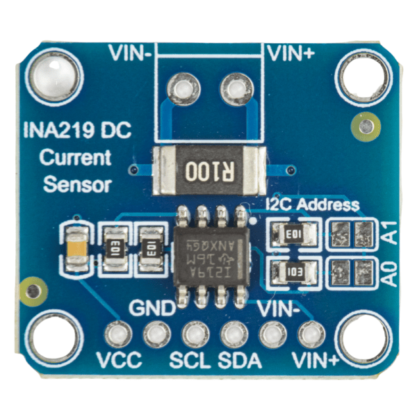
We will use a popular INA219 board, avaliable from Adafruit or other manufacturers:
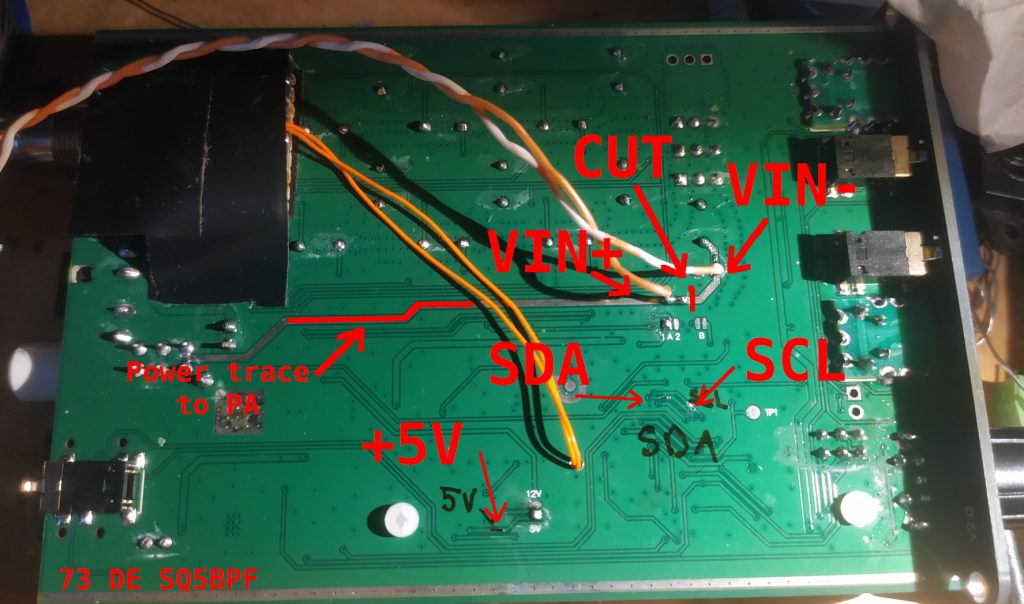
The connections are simple:
– Locate the trace that provides connect the power supply to the PA (power amplifier), cut it, connect VIN+ to the power supply side, VIN- to the PA side
– Connect to the I2C bus from the ATmega328P: PC4 to SDA, PC5 to SCL
– Connect GND to ground. Connect Vcc to +5V. Note: this will make the voltage on the I2C bus higher by 0.13V (1.4V*1k/(1k+10k)), which is not really a problem.
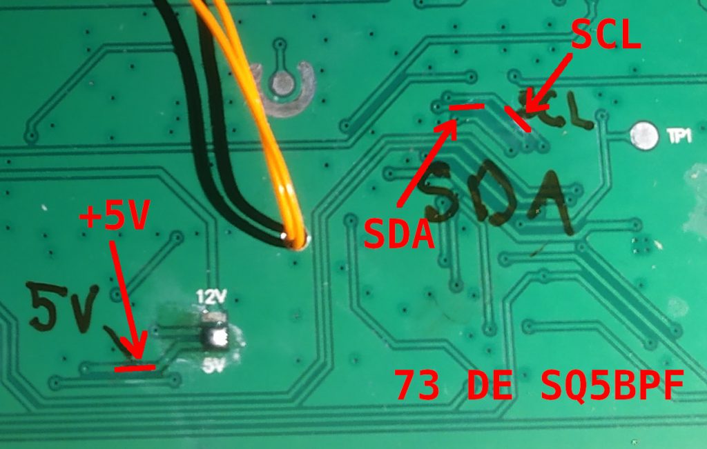
The uSDX+ has these exposed as traces on the underside of the board, for other radios you will have to trace them yourself, and if they are not available on the bottom side then route them from the top side.
Closeup:
The board is thin enough to be placed on the underside of the uSDX+ board:
Software Support
I have added INA219 support to the original uSDX sources. My changes have been incorporated into the original uSDX firmware: https://github.com/threeme3/usdx or you can use my version which may contain some changes/fixes/bugs not yet present in the original firmware: https://github.com/sq5bpf/usdx
Uncomment (remove the // before the #define) the #define SWR_METER 1 line and #define INA219_POWER_METER 1 in the usdx_settings.h file , comment the CAT and DIAG functionality, optionally do some other changes, and recompile in Arduino IDE. If there are no errors, then flash the firmware using the 6-pin ISP conector on the uSDX board (i use a uspasp-compatible programmer for that). After uploading, reset settings if the radio hasn’t done this by itself.
Calibration
The calibration settings provided in the usdx_settings.h are ok for my radio, but this can be calibrated for better accuracy.
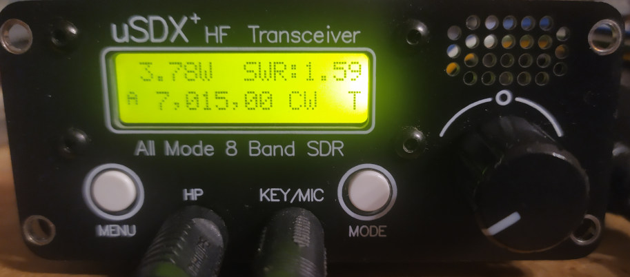
Change the 1.13 SWR Meter option to FWD-SWR, change to CW mode and transmit a constant carrier into a dummy load and power meter. The display should show forward power and SWR:
Change the 1.14 Cal. power menu setting so that the uSDX power meter shows the same power as the external power meter. Preferably do this on one the higher bands.
Now break the connection between the power trace and VIN+ and connect an ammeter between the power trace and VIN+. Change the 1.13 SWR Meter option to I-U-P (PA current, voltage, input power) and transmit.
Change the 1.15 Cal. current menu setting so that the uSDX current meter shows the same current as the external current meter:
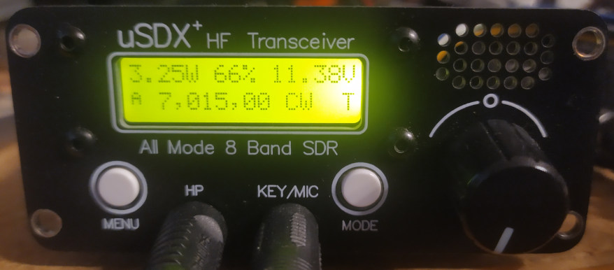
The above photo shows 3.35W PA input power, 439mA PA current and 11.37V PA voltage.
Change the 1.13 SWR Meter option to PWR-EFF and this should show the output power and PA efficiency ( 100% * PA output power/PA input power).
Using the Power monitor meter
For normal operation set the 1.13 SWR Meter option set to FWD-SWR, which shows the output power and SWR. Other useful options are PWR-EFF which shows the output power and efficiency and I-U-P which shows the input power/current/voltage (useful to estimate battery state in the field).
Substract the output power from the input power to see how much power is wasted in the finals. The BS170 has maximum dissipation of 830mW, there are 3 transistors in parallel, so if the wasted power is over 2.49W (830mW*3) they are operating over maximum specifications and can be quickly destroyed.
A class E PA stage should be tuned for best efficiency. The series inductance (not the lowpass filter/2nd harmonic filter inductance) can be changed to optimize efficiency. Change the frequency in increments of 100kHz. If the efficiency falls with frequency increase, then the series inductance should be higher (bring the windings closer to each other or even add an extra turn if this is not enough). If the efficiency falls with frequency decrease, then the series inductance is too low (spread out the windings more evenly or even remove one turn).
Note: the uSDX+ and other similar 8-band radios don’t have an output circuit for 12m, so it’s better not to optimize for this band.
VY 73
Jacek / SQ5BPF
