The (tr)uSDX transceiver has a builtin SWR meter. It will measure SWR and forward/reflected power. This is very useful in the field, because there is one less device to carry.
I have an uSDX+ transceiver from China. Let’s add the SWR meter to it too.
To make this mod you need some manual and soldering skills, a basic understanding of electronics, and the ability to compile and flash your own firmware through the 6-pin ISP connector. If you are uncomfortable with this, then just buy an original (tr)uSDX.
The (tr)uSDX schematics are available at the Manuel DL2MAN site. We can see that the SWR bridge is a Stockton bridge , with a minor twist: while the current transformer is 1:7, the voltage transformer isn’t 1:7, but 3:21. This results in the same transformation ratio, but has a higher impedance so loads the transmitter less. Quite clever.
We can get the bridge schematics from the (tr)uSDX high bands PA board:
The FWD (forward voltage) and RVS (reverse voltage) signals are connected to the ADC6 (FWD) and ADC7 (RVS) pins. These are only present on an SMD ATmega328P MCU, so if you have a radio with the DIL version (such as the DL2MAN sandwich) you can’t perform this mod.
Luckily my uSDX+ radio, and i think all uSDX radios pre-built in china, uses an ATmega328P in the TQFP32 SMD package.
The next obstacle is where to install the bridge. In the uSDX that i have the only place is on the underside of the board near the BNC antenna connector.
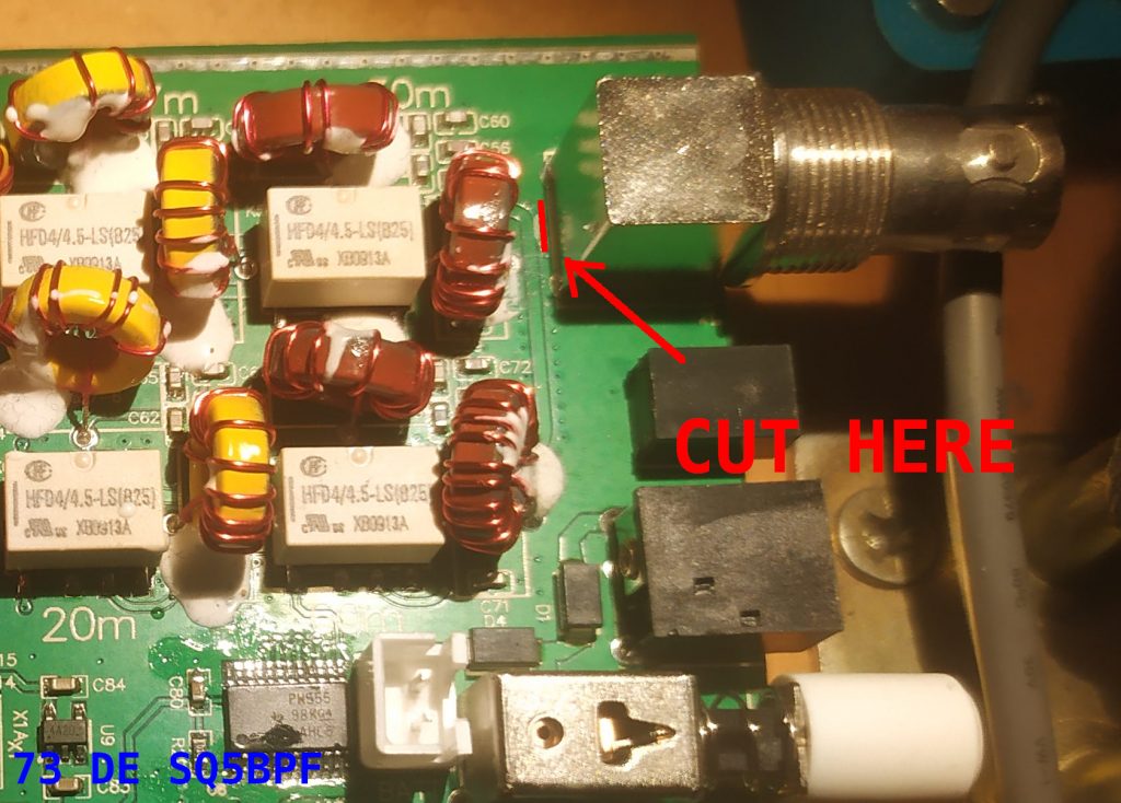
So first cut the connection to the BNC connector:
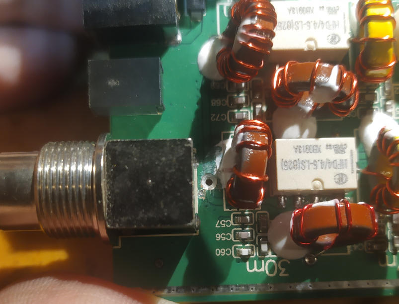
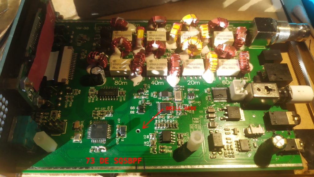
Then drill through the PCB with a 1mm (or smaller) drill bit, being extra careful not to drill through some important trace. Chamfer the hole from both sides with an about 3-4mm drill bit:
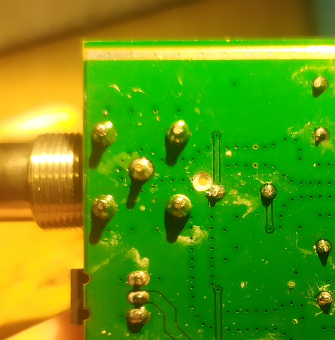
Bottom:
Next place a piece of Kynar-type wire through the hole and solder it to the transmitted output trace. Be careful to solder to both sides of the trace, because the drilling has probably cut the trace in half.
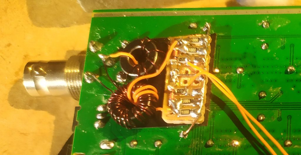
Use the soldered Kynar-type wire as the 1-turn winding of the current transformer T1. The rest of the bridge can be easily build in ugly manhattan-style on a piece of perfboard. Note: i used 47k resistors instead of 68k inthe original schematic.
Note: the underside of the transformers and bridge is insulated by black insulating tape. The bridge is also covered by insulating tape after it has been confirmed to work.
Next we need some way to connect the wires to the CPU. The easiest was to drill a 2mm diameter hole in the PCB.
Note: this is dangerous, and you don’t know how many layers this board has, so you might drill through some trace which is not visible. So best avoid what i’ve done and route the wires in some other way.
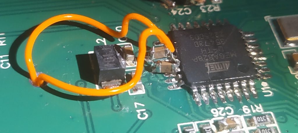
Next solder two 10nF capacitors between ground and ADC6 and ADC7. Connect the wires from the SWR bridge to the CPU: ADC6 (FWD) and ADC7 (RVS):
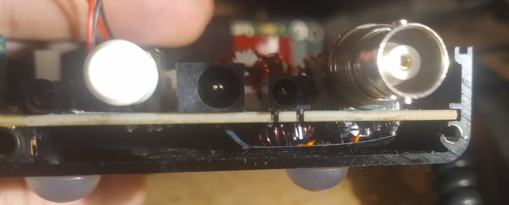
The SWR bridge fits nicely in the uSDX+ metal box on the underside of the board (with about 1mm clearance):
Software Support
There was software support for the SWR meter in the original uSDX software, however i have added the ability to calibrate the power meter using the “Cal. power” option in the menu. My changes have been incorporated into the original uSDX firmware: https://github.com/threeme3/usdx or you can use my version which may contain some changes/fixes/bugs not yet present in the original firmware: https://github.com/sq5bpf/usdx
Uncomment (remove the // before the #define) the #define SWR_METER 1 line in the usdx_settings.h file , comment the CAT and DIAG functionality, optionally do some other changes, and recompile in Arduino IDE. If there are no errors, then flash the firmware using the 6-pin ISP conector on the uSDX board (i use a uspasp-compatible programmer for that).
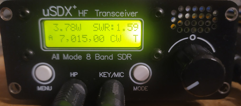
After uploading, reset settings if the radio hasn’t done this by itself, change the 1.13 SWR Meter option to FWD-SWR, change to CW mode and transmit a constant carrier. The display should show forward power and SWR:
If the readout shows very high SWR on a dummy load (or matched antenna) and/or very low forward power, then exchange the connections of one of the four windings on the FT37-43 toroids (doesn’t matter which, use the one which is the easiest to reach).
If you have a power meter and a dummy load, then connect it to the radio, and change the 1.14 Cal. power menu setting so that the uSDX power meter shows the same power as the external power meter. Preferably do this on one the higher bands.
Disclaimer: i am not responsible for anything caused by doing or not doing this modification. If you break your radio, then you’re on your own 🙂
VY 73
Jacek / SQ5BPF
