Leaking data via out of unconnected devices (both connected and unconnected) is a very interesting topic, often called “soft tempest”. Often this is the realm of absurdly costly lab equipment, source code isn’t published etc. Here i would like to demonstrate this using the simplest equipment and means, and make it very easy to reproduce.
To transmit an elecromagnetic wave one needs to have a conductor driven by a high frequency source. Various busses are used: monitor cables, pci buses etc. Here i propose the use of ethernet.
An ethernet cable consists of 4 twisted pair lines with 100ohm impedance., which carries RF signals in the tens to hundredths MHz range. Any imperfections in the cable (asymetry etc) or in the interface will cause radio signals to be radiated.
Signals can be modulated using different methods. Here i will use morse code for simplicity. This also allows one to judge the signal to noise ratio by just listening. It is also possible to decode it by ear without additional devices if one knows morse code, if not there is a lot of software that can do it (although usually with much worse performance than an experienced human operator).
Transmission is implemented via very simple shell scripts. Only bash, ethtool and ping is needed. This enables the script to be used easily on embedded devices and other platforms where shipping binaries, installing a python environment etc might be a problem.
The proof-of-concept scripts are avaliable at https://github.com/sq5bpf/etherify
Etherify 1 – transmitting by switching speed
Various ethernet speeds have different modulation speeds, types and encoding. By switching between we can modulate the RF signal leaking from the wires.
10base-T uses manchester encoding with 10MHz symbol rate. This is used as the space signal (logical 0).
100base-T uses 4B5B encoding with NRZI at 125MHz symbol rate . This results in an easy to receive signal around 125MHz, this is used as the mark signal (logical 1).
Ethernet transmits an idle sequence when no packets are carried, so the signal is constant. No packets have to be transmitted for the signal to be present, on the speed of the interface has to be changed.
The transmission is implemented by a simple bash script, which sends the content of a short text file given as the argument, or “etherify demo” if none is given. The signal can be received as morse code around 125MHz, please use USB or CW mode in the receiver and use a narrow filter.
Demo:
Ensure that the two raspberry PIs are connected and that there is an ethernet link between them (signalled via the LEDs).
Run as root:
./etherify1
to transmit “etherify demo” or to exfiltrate the contents of /tmp/secret.txt
./etherify1 /tmp/secret.txt
Listen to the signal at 125MHz as described below.
The is decodable by ear with a simple Moxon directional antenna and a ham radio receiver (SDR could be used too).
This results in a strong signal at 15m distance:
The results at 100m distance (weak signal, please use headphones):
If in doubt let an experienced amateur radio operator decode it. I was not able to decode the signal at 100m with software.
Etherify 2 – transmitting by sending data
Sending a stream of data at 1Gbps also produces a detectable signal change at 125MHz. There may be other frequencies where the signals were more readable, but equipment was avaliable to receive at 125MHz. This probably works by loading the supply voltage when the packets are generated. A change of voltage probably changes the frequency of some clock slightly, thus generating FSK (F1A to be exact). Note that this doesn’t work with all hardware, which could be explained by the hypothesis about the frequency being modulated by the interface load.
A large volume of traffic represents a logical 1, while no traffic represents logical 0.
The transmission is implemented as a simple bash script, which sends the content of a short text file given as the argument, or “etherify demo” if none is given. The signal can be received as morse code around 125MHz, please use USB or CW mode in the receiver and use a narrow filter, also AM mode can be used.
Demo:
Ensure that the two raspberry PIs are connected and that there is an ethernet link between them (signalled via the LEDs). Set one raspberry PI to 192.168.1.1/24 and the other to 192.168.1.2/24 (the IP address can be changed in the etherify2 script). Ensure that the two raspberry PIs have IP connectivity and can ping each other, and that he interface rate is 1Gbps.
On the 192.168.1.2 raspberry PI run as root:
./etherify2
to transmit “etherify demo” or to exfiltrate the contents of /tmp/secret.txt
./etherify2 /tmp/secret.txt
Listen to the signal at 125MHz as described below.
The signal was decodable by ear at a distance of 30m with a simple Moxon directional antenna and a ham radio receiver.
This results in a strong signal at 15m distance:
And a readable signal at 30m:
20201119: Recently i’ve been unable to reproduce this demo in a reliable way at 125MHz, however it worked perfectly at the 4th harmonic (500MHz). Always check all harmonics of the signal, some may work better than others.
Etherify 3 – it turns out only one Raspberry PI is needed
It seems that only one Raspberry PI 4 can transmit a signal from it’s ethernet port, even without an ethernet cable conencted. I sincerly hope this is a problem with this particular specimen that i have, and not with all of them.
This article is getting long, so i’ve split it out to a different page, please read:
Etherify 3 – the PI 4’s dirty little secret
Etherify 4 – the transmission can be done with normal laptops
Normal laptops can leak a signal too, even the well shielded ones. So this is not only a Raspberry PI 4 problem, although the signal is orders of magnitude weaker.
This article is getting long, so i’ve split it out to a different page, please read:
Etherify 4 – back to earth with “normal” ethernet hardware
Etherify 5 – Etherify 4, but implemented on network equipment
If a laptop can leak signals, so will other network equipment (like ethernet switches) will also leak signals.
This article is getting long, so i’ve split it out to a different page, please read:
Etherify 5 – switching the switches
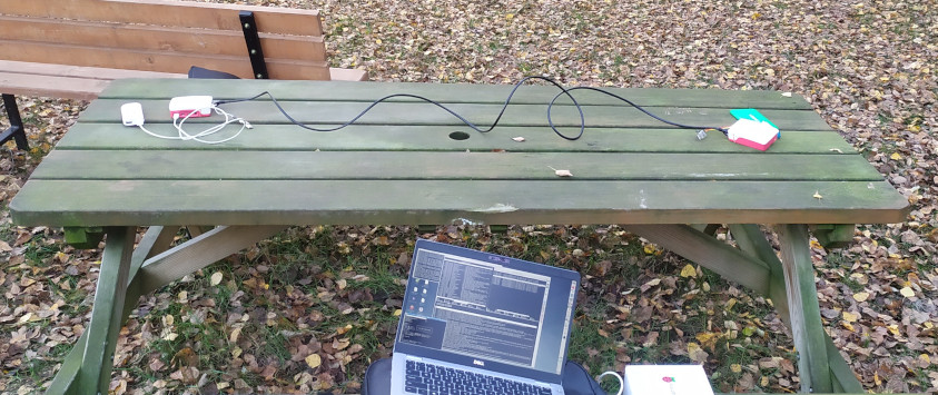
Equipment used and experiment description
The RF radiation differs with different equipment and ethernet cable type being used. In order to make this demo reproducible i used two Raspberry PI 4, because it makes it easy for everyone to obtain the exact hardware that was used for this experiment. The raspberry PIs were connected using the ethernet cable supplied with the official Raspberry PI 4 starter kit. The stock Raspbian 10 operating system, which was supplied on the SD cards in the Starter Kit, was used. The devices were accessed via the serial console.
Power was provided via powerbanks. This was to avoid a connection to the mains voltage, because the powerline could be an unintentional radiator.
The Raspberry PIs were laid on a wooden bench about 1.4m from each other.
The experiment was conducted in an electromagnetically quiet area.
The signal was received via a Moxon antenna built for 125MHz and a Yaesu FT-817 transceiver with a 500Hz CW filter. Morse code was received and decoded by ear.
This is a link to the description of antenna used: Moxon antenna for 125MHz
The experiments can be repeated with other devices with ethernet ports, for example two laptops, running any linux distribution and the required tools installed (most will come with them out of the box). The devices should be able to establish an ethernet link very quickly upon switching speed. An SDR receiver can be used for reception, with any antenna that can receive 125MHz (test first at close range). Morse code decoding can be done via software, for example fldigi [3].
The easiest receive setup would probably be gqrx with an rtl-sdr dongle, and fldigi for deciding the signals. If the signal is not decoded, it should be played to someone who can receive morse code by ear. Often such person will be able to decode it with ease.
The experiment should be first conducted in an electromagnetically quiet area, nearby ethernet networks will generate a lot of interference. If testing in the vicinity of other ethernet networks move the antenna closer, and reduce the receiver gain as much as possible.
How to replicate with your own hardware
This can be replicated with other ethernet hardware, but with varying results.
The speed at which the ethernet hardware can renegotiate different speed sets the maximum speed of etherify 1 transmission. The ethernet port on the raspberry pi 4 can change speed very quickly. Other hardware will have a delay when chaging speed, for example on an Dell Latitude 5310 running with Debian bullseye (e1000e 3.2.6-k driver) it takes about 5 seconds to change speed. Lower modulation speed means lower datarate, but also better signal/noise when decoding.
The clock frequency modulation under packet load observed on the raspberry pi 4 (etherify 2) is specific to the raspberry pi 4. However loading the interface with packets often has effects on the electromagnetic spectrum on different hardware.
To check your hardware:
- look at the spectrum around 125MHz
- ensure that the interface is up
- change speed with ethtool to 10Mbps, 100Mbps, 1Gbps and observe the spectrum
- try enabling/disabling eee (energy efficient ethernet), observe the effects at different speeds
- try loading the interface with packets, observe the effects at different speeds
- look at different ethtool settings and module options, especially those concerning power saving, carrier delay etc.
- allow a few seconds after changing each parameter, on some interfaces it takes some time to change parameters
- keep in mind that both ends of the ethernet link have an effect on he transmission. For experiments it’s best to use the same hardware on both ends.
If you find something interesting, then please send me an email.
Discussion
The signal was shown to be decodable by ear at 100m for etherify 1, and 30m for etherify 2. This was done via a simple antenna and modest receiver. An antenna with more gain and better receiver would surely yield better range.
Nearby ethernet networks will generate a lot of interference at the same frequencies. The 125MHz frequency falls in the 108-137MHz air band, and one can expect interference from strong signals on nearby frequencies from nearby airplanes and airports. Therefore first tests should be conducted in areas with less interference, such as outdoor areas or underground parking lots.
The 125MHz frequency was chosen because of avaliable equipment. It would be hard for one person to hold and operate an antenna, laptop and SDR receiver. Other frequencies may be better.
Etherify 1 yields better range, however etherify 2 may enable to use a device located somewhere else in the network as the transmitter. This device may be physically closer to the receiver or may have greater leakage from the ethernet cable. Etherify 2 can be exploited as a non-root user by flooding the network with UDP datagrams or possibly other data.
The “software” side is intentionally a very primitive silly hack.
I haven’t done an extensive search for similar prior publications, but a few quick searches didn’t yield any results. If you know of any, please let me know.
If you cite this, please include the webpage address and attribute Jacek Lipkowski (SQ5BPF). Email can be sent to my_callsign @ this_domain.
[1] https://en.wikipedia.org/wiki/Ethernet_over_twisted_pair
[2] https://blog.telegeography.com/luminiferous-ether-how-ethernet-got-its-name-local-access-pricing-service
[3] http://www.w1hkj.com/