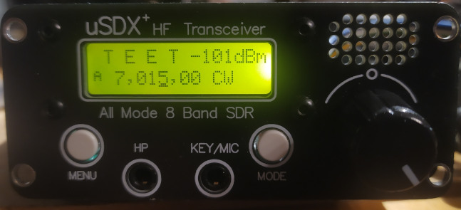
The uSDX+ is a nice little transceiver from china based on the uSDX project. It is cheap, works on 8 bands, is based on opensource software, and has enough place inside the case to do some modifications. And if it breaks, it is easy to fix (probably easier than many analog radios).
So let’s see what we can modify in this radio.
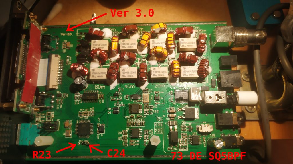
The following modifications will be for the uSDX+ (uSDX plus), with the board marked Ver 3.0, but other radios may be similar and similar modifications may apply.
R23 modification
The uSDX has an unpopulated pad marked R23. Solder 100k there. This resistor is used to discharge the capacitor of the filter that provides the bias to the class-E amplifier. Soldering the resistor enhances carrier power control, and as a result makes SSB sound a tiny bit better.
Note: you may have to set PA Bias max to a higher value when this resistor is soldered.
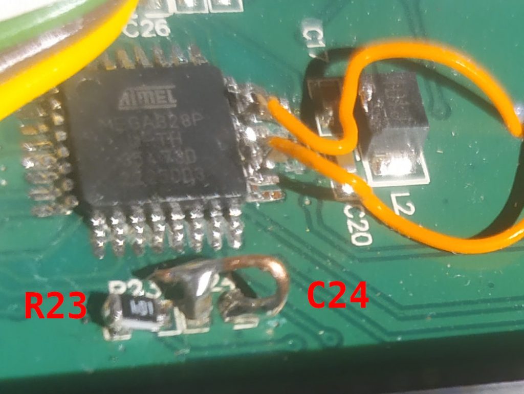
C24 modification
C24 is connected to the MOSI line, which is used also when flashing the MCU via the ISP. Many descriptions say that it should be disconnected while flashing, or disconnected entirely.
We should not disconnect it, because that line goes to the PA jack. But we can solder the 10nF capacitor vertically and solder a piece of wire that will connect it to ground. This wire will be easy to temporarily unsolder if we ever have a need to do it.
It turns out the usbasp programming interface has a low enough output impedance for this not to be a problem, but it might be useful to disconnect it if other programmers are used.
Shielding fix
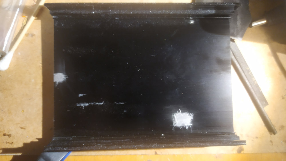
The uSDX+ is housed in a nice anodized aluminum case. But aluminium oxide is not conductive, so this case doesn’t actually work like a shield. Is this a problem? Maybe no, because the (tr)uSDX transceiver is housed in a plastic case with no shielding. But since we have a nice metal case, might as well use it as shielding.
Scrub the soldermask around the source of the PA fet and around the BNC jack so that a contact can be soldered there. Make a contact from brass strip and bend it so that it will make good contact with the metal case.
Scrub the aluminum oxide layer to expose raw aluminum where the brass strips touch the case.
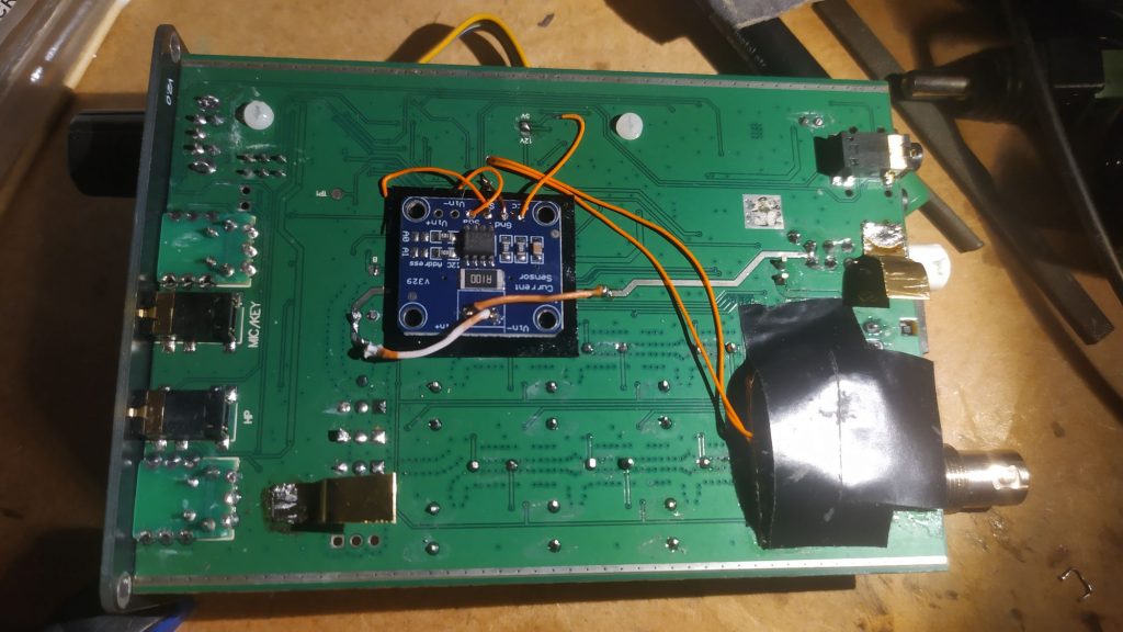
Adding an SWR meter and a PA power monitor
I’ve detailed the modifications here:
Adding an SWR meter to a chinese uSDX+ transceiver
Adding an INA219 power monitor to a chinese USDX+ transceiver
Demo of both mods:
Tuning the uSDX output network
The class-E amplifiers have to be tuned for best efficiency. Efficiency can either be displayed via the INA219 power monitor mod (shown above), or can be calculated manually:
– Connect a power meter to the uSDX
– Look at the current in RX, this is usually 40-50mA (call this Irx)
– Transmit a carrier in CW
– Assume that the PA current during transmit is Itx-Irx (where Itx is the current during transmit)
– Calculate the input power as Pinput=Vsupply*(Itx-Irx) (Vsupply may be the power supply voltage, or in case of the uSDX+ it is power supply voltage-0.7V where 0.7V is the silicon diode voltage drop)
– Calculate the efficiency as Poutput/Pinput*100%
Doesn’t matter if the efficiency is calculated manually or just shown by the device (which i would recommend), we want to tune for maximum efficiency for each band on the center frequency of the range of frequencies that we will mostly use (center of band, or maybe center of the first 100-200kHz of the band for CW operators)
The tuning procedure is:
– Set the power supply to 12V
– Change the frequency in increments of 100kHz
– If the efficiency is declining with increase of frequency, then increase the inductance of the coil which is connected to the drain. If the efficiency is declining with decrease of frequency, then decrease the inductance of the coil which is connected to the drain. Making the windings closer to each other increases the inductance, spreading them more evenly on the core decreases it.
It is much easier with having the efficiency calculated on the display. Just change the inductance to achieve the best possible efficiency.
I have increased the efficiency of the PA stage to over 70% on the high bands, and more on the low bands. For some this is around 90%.
Increase power by changing the output transistor
The output power depends on the power transistor being used. These are being used:
– 3 * BS170 – this is the usual setup. I have been asked to fix a (tr)uSDX with the PA blown, so guess it’s not that bulletproof
– IRLML2060 – great (and very small) transistor when the matching networks are tuned for the frequency of operation. Unfortunately it will often fail when mismatched, especially in the field. See SV9/SQ5BPF with uSDX part 2
– IRF510/IRF520/IRF530 – these transistors have very big gate capacitance. Also not good on the higher bands.
– IRLL110 – i have tried this transistor based on Pmax and Idmax. Not great on the higher bands, but works great on 20m and below (and probably higher, but then i didn’t have the modified radio o show efficiency).
– FDT86256 – looks like a great fet. The maximum power and current are bigger. If the tuning is good, then this is probably the best output device.
Want more mods for your uSDX version?
I can’t possibly support all uSDX versions and make mods for them, because i don’t have them. If you have an unused uSDX, and would like to see new mods for it, you can donate it. Even a broken one will do if it’s easily fixable (for example PA transistor failure). If you have such a radio, please send email to usdx1@lipkowski.org
