This is the third part of articles about the Great Seal Bug (also called “The Thing”). These articles will cover: history, theory of operation and a practical reconstruction of this device. This part is about building a working copy of the Great Seal Bug
To my knowledge this is the only publication about making a wirking replica of the Sreat Seal Bug. https://www.vintagespycraft.com/ shows a beautifully looking model, however the emphasis was on making it a nice looking exhibit, and not on making it work (but look at this site anyway, the model is a work of art).
In 1945 this was super-secret, ultra-novel military technology. Building and operating it required special materials and access to ultra-secret hardware. So is it possible to do this in 2022 on an amateur budget? Surely not.
But radio amateurs have a long history of doing “impossible” things, part because of their ingenuity, and part because of their ignorance (they simply don’t know something can’t be done). So lets try anyway 🙂
The construction of the Great Seal Bug is described in the top secret FBI document “Drawing and Photographs. Russian Resonant Cavity Microphone” [1] from 1952, which was declassified in 2019 (after 67 years):
I will use most of this design, but won’t attempt to make a 100% copy. Instead I will try to make the device from commonly avaliable materials, using commonly avaliable tools. Also it should be as cheap as possible, even if that means sacrificing performance or making it look ugly (and it will!). Also I will try to document my errors.
Choice of frequency
The original design is for 1700 MHz, which was free in 1945, but now is in the uplink frequency range for GSM DCS. Transmitting there would be radio piracy, and also very stupid because the mobile phone companies paid a lot of money to use these frequencies, and therefore actively monitor for interference.
Fortunately I am a licensed radio amateur (my callsign is SQ5BPF), so I can legally use the 23cm amateur radio band (1240-1300 MHz) for my experiments. This is a good choice, because I already have made some equipment for this band, and also the cheap rtl-sdr dongle covers this band.
If I wasn’t licensed I would probably use the 868 MHz or 2.4 GHz ISM bands.
My choice of frequency is 1296MHz, so every dimension has to be multiplied by 1700/1296 = 1.3
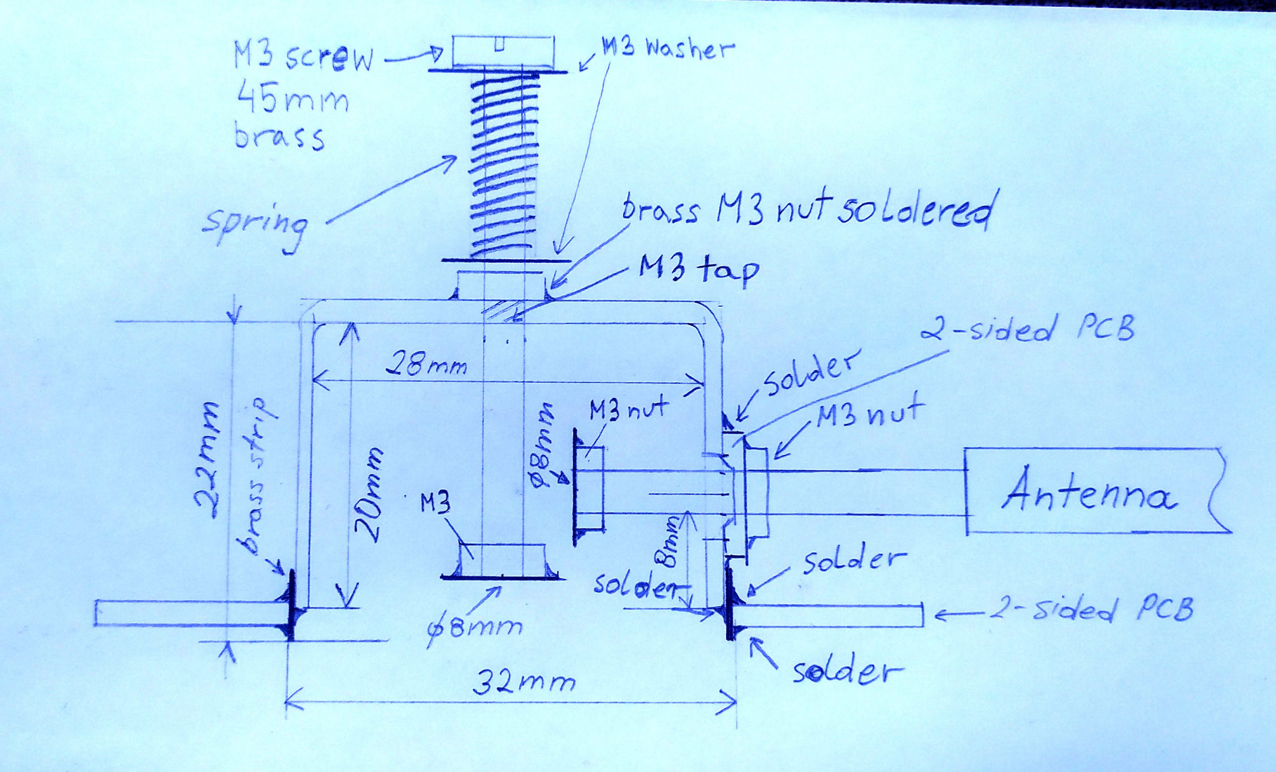
The following ugly drawing shows the calculated dimensions.
Choice of materials
I will try to use low-loss materials: copper and brass.
Amateur radio operators have used microwave filters made from copper pipe caps for a long time. They are cheap, simple to make, easy to tune, and forgive a lot of construction errors. These “pipe cap filters” were pioneered in 1988 by Roman Wesołowski DJ6EP (Polish callsign SO3EP and ex SP3GDQ). There are many examples of such filters on the internet (search for “pipe cap filter”), some here:
https://www.wa5vjb.com/references/CheapMicrowaveFilters.pdf
http://w1ghz.org/filter/Pipe-cap_Filters_Revisited.pdf
Naturally i will also use a pipe cap.
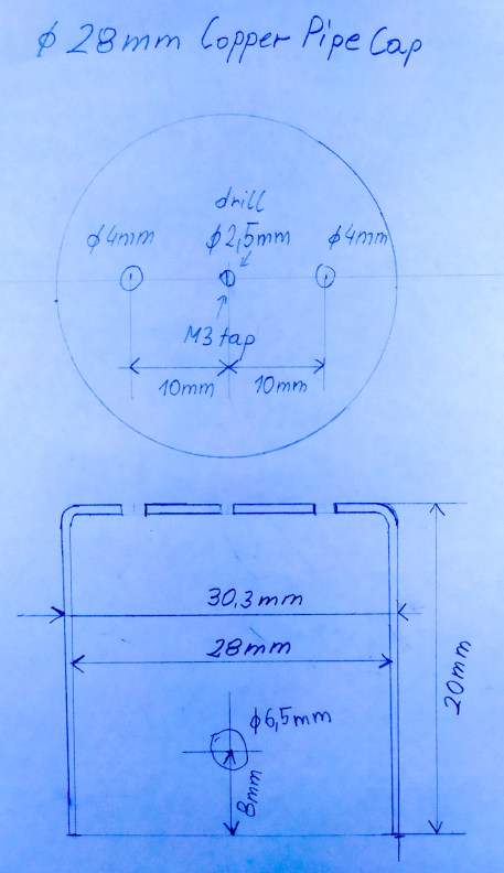
The best pipe cap i could find is a 28mm pipe cap (for 1″ pipes). These have 28mm internal diameter, 30.3mm external diameter and 20mm depth:
Unfortunately this project has some problems, but all are solvable:
- We want 22mm depth, and this has only 20mm. This can be extended by soldering a brass strip on the outside (this will be shown later).
- There is nothing to hold the microphone membrane and provide good good electrical contact with the whole circumference of the cylinder. This will be done with two double-sided copper laminate used for PCBs.
- We need something dielectric with good microwave properties to hold the antenna. Originally it was a special piece of plastic with inside thread. We will just use double-sided FR4 copper laminate.
- It would be nice to be able to try different antenna lengths. We will just use a telescopic antenna.
- Were do we get an ultra-thin silver plated membrane? We’ll just use aluminum foil, the cheapest kinds are very thin. This is not the best choice, but best i had (thin copper foil, preferably silver-plated would be much better).
Preparing the pipe cap
Below is a drawing where the pipe cap should be drilled:
The pipe cap was then cleaned with steel wool and dishwashing detergent.
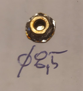
The 2.5 mm hole in the center was tapped with a M3 thread. Next a steel M3 screw with a brass M3 nut is screwed from the outside into this hole, and the brass nut is soldered to the pipe cap. The steel screw is removed after soldering. All soldering of the pipe cap is best done with a high power soldering iron, I used a 300W soldering iron.
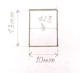
The antenna mount is made from a rectangular 10mm x 13mm piece of double sided PCB laminate (FR4), with a 2.5mm hole drilled in the center. The copper around one side of their hole is removed with a very shallow drilling
This 2.5mm hole is tapped with a M3 thread. Next a steel M3 screw with a brass M3 nut is screwed into the hole, and the brass nut is soldered to the copper laminate.
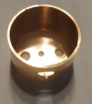
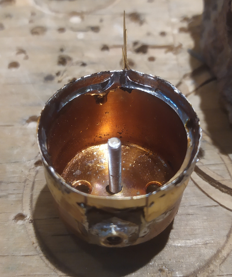
This antenna mount is soldered to the hole on the side of the pipe cap. After soldering excess copper foil around the brass nut is removed with a file. Below is the antenna mount with the internal elements mounted for a test. Check the mount with an ohmmeter, there should be no electrical contact between the antenna and the pipe cap.
A 10mm brass strip, 0.3mm thick, is soldered to the outside of the pipe cap, so that the internal height is 22mm (2mm greater, because pipe cap internal height is 20mm). The brass strip has a rectangular hole cut out so that it doesn’t go over the antenna mount. The area of the pipe cap which is under the brass strip should be tinned before soldering the brass strip. Use a high power soldering iron for this.
Cut and file away the extra brass, so that the outside is round.
Next make a holder from two rectangular pieces of double-sided PCB board, with 3.5mm holes 5.5mm from the sides, and a 32mm hole in the middle. The two pieces should fit exactly over each other:
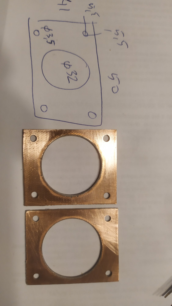
Put the pipe cap into the big hole, so that the brass strip sticks out a bit (around 0.5 – 1mm). Solder the brass strip to the copper PCB.
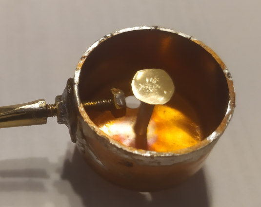
Prepare two brass disks of around 8-9mm diameter, and solder them to brass M3 nuts:
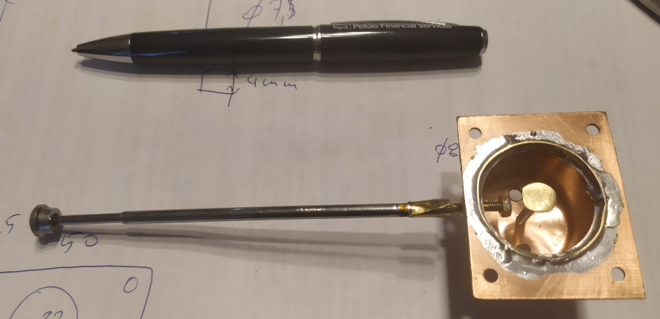
Solder a brass 40mm long M3 screw to a telescopic antenna. The exact method will depend on the antenna type. I made an adapter from a piece of brass strip surrounding the antenna and the screw head.
Now prepare for the final assembly. File away excess solder. Clean everything with steel wool with detergent, wash with water, and then clean with alcohol. If you want to silver-plate the inside of the pipe cap, the screws and the capacitance disks, you can do so now (and after silver-plating wash with water and alcohol again).
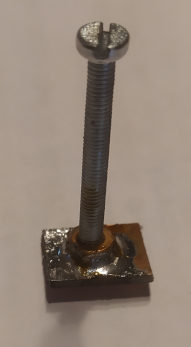
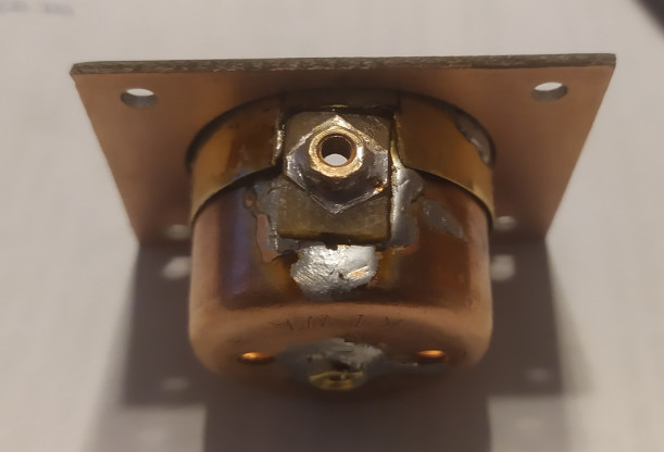
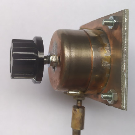
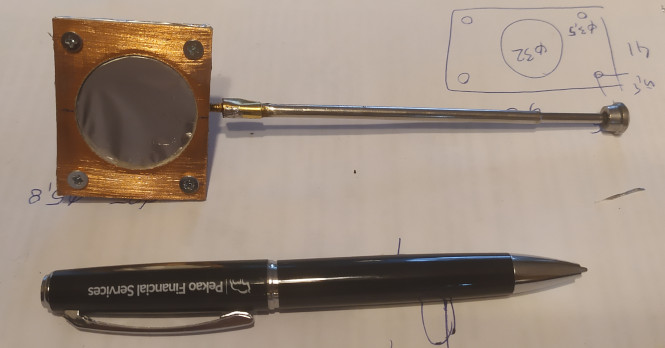
The tuning screw is a 45mm brass screw. I also added two washers, a spring (from a ball-point pen), and some nuts at the end.

A potentiometer knob can be mounted on the nuts at the end of the screw:
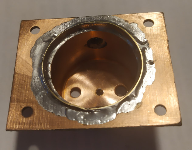
Assemble everyting inside:
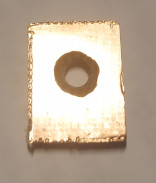
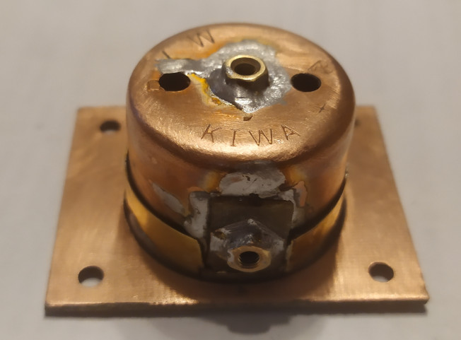
Install the thin foil membrane. I used cheap aluminium foil here (usually the cheaper foils are thinner), silver side to the pipe cap. Try to have the foil as straight as possible. Put the other PCB laminate holder on it, and screw the two together with M3 screws.
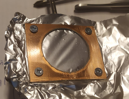
And cut away the extra foil:
Congratulations! You’ve just built a russian top-secret cold-war passive microphone.
But does it work? There is only one way to find out (in the next article).
Author: Jacek Lipkowski SQ5BPF
Literature:
[1] https://www.cryptomuseum.com/covert/bugs/thing/files/GREAT_SEAL_BUG.pdf